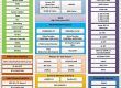
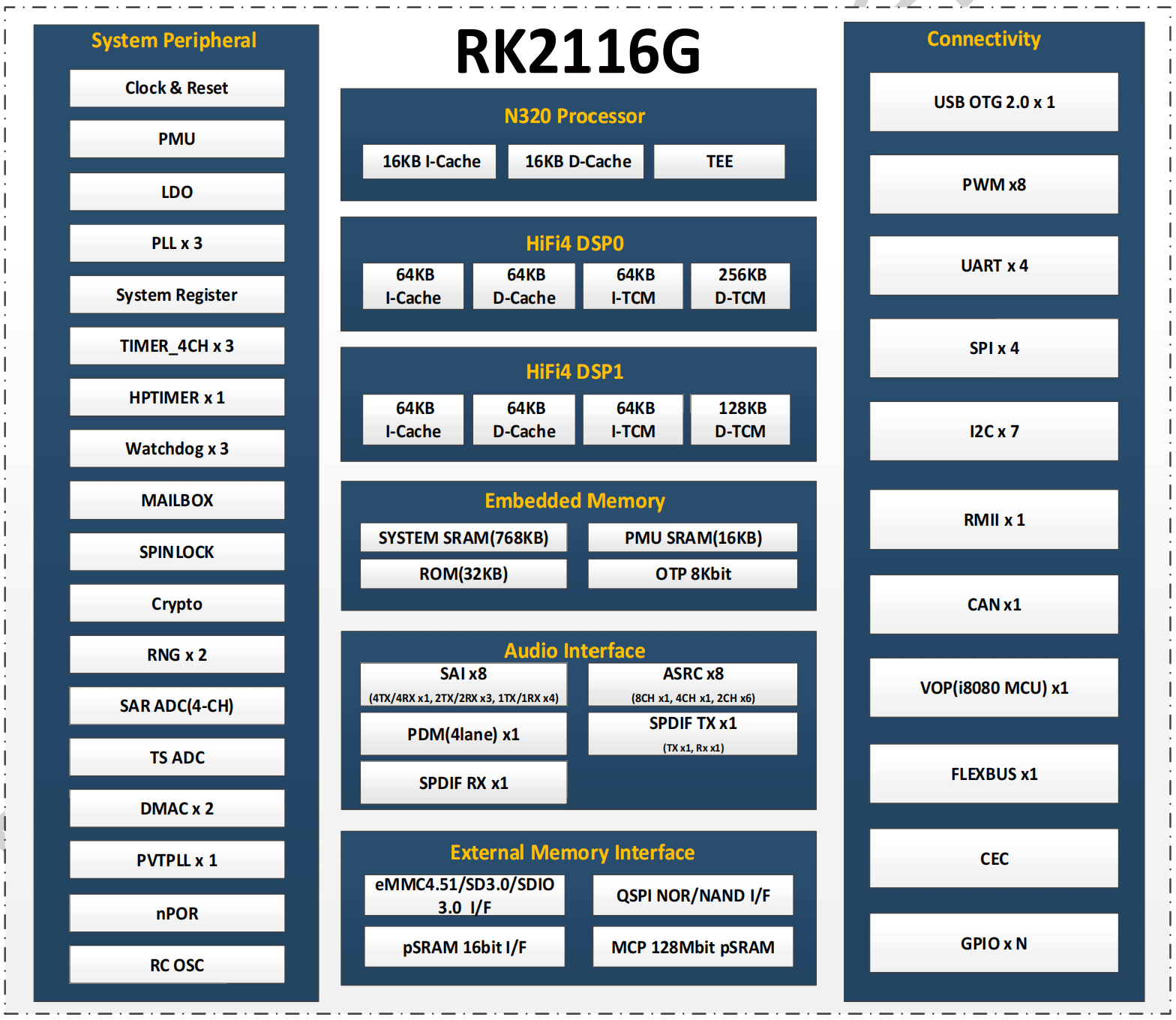
RK2116G是一款高性能双核HiFi4 DSP处理器,专为智能语音交互、音频输入输出处理及其他数字多媒体应用而设计。
RK2116G处理器集成一颗N320 RISC-V内核处理器,可运行操作系统、UI渲染及应用程序协议栈等功能。内置768KB系统内存并支持片内执行(XIP)闪存接口,使RK2116G能灵活适配各类应用开发需求。
RK2116G集成了丰富的外设接口,包括VOP显示输出、SAI音频总线、PDM麦克风输入、SPDIF数字音频、USB2 OTG、RMII以太网、CAN总线、CEC消费电子控制等,既能满足多样化应用开发需求,又可显著降低硬件开发复杂度与成本。
此外,该处理器还内置16MB pSRAM静态随机存储器。
Microprocessor
⚫ One N320 RISC-V processor
⚫ Support Zc*, Zicond and Bit-Manipulation Instruction Set Architecture Extension
⚫ Support Private Timer Unit
⚫ Support Enhanced Core Level Interrupt Controller
⚫ Support one Multiplier, one Divider and one Floating Point Unit
⚫ Support configurable Physical Memory Protection
⚫ Support configurable Trust Execution Environment
⚫ Support 16KB I-Cache and 16KB D-Cache
⚫ Support standard 2-wire cJTAG debug interface
DSP
⚫ Dual core HiFi4 DSP processor (DSP0, DSP1)
⚫ Dual Load/Store, 4 VLIW Slots, 64-bit SIMD
⚫ 4 MAC 32×32, 4 MAC 24×24, 8 MAC 32×16, 8 MAC 16×16 per cycle
⚫ Two 2-Way SIMD VFPU
⚫ 64KB ITCM, 256KB DTCM, 64KB I-Cache, 64KB D-Cache for DSP0
⚫ 64KB ITCM, 128KB DTCM, 64KB I-Cache, 64KB D-Cache for DSP1
⚫ One isolated voltage domain for DSP DVFS
Memory Organization
⚫ Internal on-chip memory
■ BootROM
■ System SRAM
■ PMU SRAM
⚫ External off-chip memory
■ pSRAM
■ SPI Nor/Nand Flash
■ SDMMC (eMMC/SD Card)
Internal Memory
⚫ Internal BootRom
■ Support system boot from the following device:
♦ SPI Flash interface
♦ SDMMC(eMMC/SD Card) interface
■ Support system code download by the following interface:
♦ USB OTG interface (Device mode)
RK2116G Datasheet Rev 1.0
♦ SPI0 interface (Slave mode)
♦ I2C0 interface (Slave mode)
♦ UART0 interface
⚫ Internal SRAM
■ 768KB System SRAM
■ 16KB PMU SRAM
External Memory or Storage device
⚫ pSRAM Interface
■ Support master role
■ Support transfer data from/to Xccela pSRAM device
■ Support transfer data from/to Hyperbus pSRAM device
■ Support up to 1 chip select
■ Support x8,x16 data bits mode
■ Support DDR mode
⚫ Serial Flash Interface
■ Support transfer data from/to SPI flash device
■ Support x1, x2, x4 data bits mode
■ Support SDR mode
■ Support XIP (eXecute In Place)
■ Support up to 1 chip select
⚫ SD/MMC Interface
■ Compatible with standard iNAND interface
■ Compatible with eMMC specification 4.51
■ Compatible with SD3.0, MMC ver4.51
■ Compatible with SDIO3.0 protocol
■ Data bus width is 4bits
System Component
⚫ CRU (clock & reset unit)
■ One oscillator with external crystal input
■ One internal low frequency RC clock
■ One internal power on reset circuit
■ Support single-end 32.768KHz clock input/output from/to GPIO
■ Support PLL control and generate various clock frequency for chip
■ Support reference clock of PLL come from GPIO single-end clock input
■ Support clock gating control for individual components
■ Support global soft-reset control for whole chip, also individual soft-reset for each component
⚫ PMU(power management unit)
■ Three separate digital voltage domains (DSP_DVDD/CORE_DVDD/PMU_DVDD)
■ Multiple configurable work sleep modes to save power consumption by different frequency or automatic clock gating control or external power on/off control
⚫ Timer
■ Twelve 64bits timers with interrupt-based operation
■ One 64bits timer for low power mode application
■ Support two operation modes: free-running and user-defined count
■ Support timer work state checkable
⚫ PWM
■ 8-channels PWM with interrupt-based operation
■ Support capture mode
■ Provides reference mode and output various duty-cycle waveform
■ Support continuous mode or one-shot mode
■ Support one channel IR TX and one channel IR RX application
■ Support one clock frequency calculation engine and one clock free running counter
■ Support three channels as waveform generation through lookup table
■ Support three channels as led controller
⚫ Watchdog
■ Support three 32-bit watchdog counter
■ Counter counts down from a preset value to 0 to indicate the occurrence of a
timeout
■ WDT can perform two types of operations when timeout occurs:
♦ Generate a system reset
♦ First generate an interrupt and if this is not cleared by the service routine by
the time a second timeout occurs then generate a system reset
■ Programmable reset pulse length
■ Totally 16 defined ranges of main timeout period
⚫ Mailbox
■ One Mailbox to service different core’s communication
■ Support sixteen mailbox elements, each element includes one data word, one
command word register and one flag bit that can represent one interrupt
⚫ Spinlock
■ Support spinlock registers for software to realize resource management
⚫ DMA
■ Support two embedded DMA controllers
■ Support data transfer types with memory-to-memory, memory-to-peripheral,
peripheral-to-memory
■ Support 36 logic channels and 4 physical channels for each DMA controller
⚫ Secure System
■ Cipher engine
♦ Support SHA-1, SHA-256/224, MD5 with hardware padding
♦ Support HMAC of SHA-1, SHA-256, MD5 with hardware padding
♦ Support AES-128, AES-192, AES-256 encrypt & decrypt cipher
♦ Support AES ECB/CBC/OFB/CFB/CTR/CTS/XTS/CCM/GCM/CBC-MAC/CMAC mode
♦ Support up to 4096 bits PKA mathematical operations for RSA
■ Support two 256 bits RNG output
■ Support secure boot
■ Support secure debug
■ Support secure OTP
■ Support secure OS
■ Support bus firewall
Video Output Processor
⚫ Support RGB888/RGB565 source data format
⚫ Support RGB888/RGB565/RGB666 display data format
⚫ Support i8080 MCU serial interface
⚫ Support max output resolution 480×480
Audio Interface
⚫ SAI
■ Support eight SAI components
■ Support audio protocol: I2S, PCM, TDM
■ Support up to 128 slots available with configurable size
■ Support slot length 8 to 32 bits configurable
■ Support slot valid data length 8 to 32 bits configurable
■ SAI0 support up to four lane transmitter and four lane parallel receiver
■ SAI1~3 support up to two lane transmitter and two lane parallel receiver
■ SAI4~7 support up to one lane transmitter and one lane receiver
■ Support combine different SAI component to meet more transmitter and receiver lane
⚫ PDM
■ Support PDM master receive mode
■ Support 5 wire PDM interface with one is clock and 4 data line
■ Support up to 8 mono microphones
■ Support 16~24 bits sample resolution
⚫ SPDIF
■ Support SPDIF TX x 1
■ Support SPDIF RX x 1
■ Support 16bits/20bits/24bits resolution
■ Support linear PCM mode (IEC-60958)
■ Support non-linear PCM transfer (IEC-61937)
⚫ ASRC
■ Support eight ASRC components
■ Support fixed length conversion mode and real time conversion mode
■ Support asynchronous sample rate clock for real time conversion mode
■ ASRC0 support 8 channel sample rate converter
■ ASRC1 support 4 channel sample rate converter
■ ASRC2~7 support 2 channel sample rate converter
■ Support combine different ASRC component to meet more channel sample rate converter
⚫ Audio CODEC
■ ADC
♦ Support four channel 24 bit ADC microphone input
♦ Support Differential mode, Single-end mode and Pseudo-differential mode
♦ Sample rate up to 192KHz
♦ Support Digital HPF for DC offset cancel
♦ Support two MIC Bias output
■ DAC
♦ Support four channel 24 bit DAC lineout output
♦ Support Single-end mode
♦ Sample rate up to 192KHz
Connectivity
⚫ RMII 10/100 Ethernet Controller
■ Support one Ethernet Controller
■ Supports 10/100-Mbps data transfer rates with the RMII interfaces
■ Supports both full-duplex and half-duplex operation
⚫ USB 2.0 OTG
■ Support one USB 2.0 OTG port
■ Compatible with USB 2.0 specification
■ Supports high-speed (480Mbps), full-speed (12Mbps) and low-speed (1.5Mbps) mode
⚫ FLEXBUS interface
■ High Speed Interface
♦ Support transfer data from internal memory to GPIO by DMA
♦ Support transfer data from GPIO to internal memory by DMA
♦ Support Multiplexing TX clock and RX clock and Multiplexing TX data and RX data
♦ Support TX only mode, RX only mode, TX then RX mode
♦ Support clock free running mode and following data mode
♦ Support TX data width 1, 2, 4 bit configurable
♦ Support RX data width 1, 2, 4 bit configurable
♦ Support continue transmission mode and fix length transmission mode
♦ Support one chip selection function
♦ Support TX clock auto gating
■ Low Speed Interface
♦ Support two channels low speed interface
♦ Support software configurable as I2C, UART, SPI and SAI interface protocol for each channel
⚫ SPI interface
■ Support four SPI interface
■ SPI0/SPI3 support serial-slave mode
■ SPI1/SPI2 support serial-master and serial-slave mode, software-configurable
■ Support direct connection from SPI0 interface to Serial Flash Interface
⚫ I2C interface
■ Support seven I2C interface
■ I2C0 support as slave mode
■ I2C1~6 support as master mode
■ Support data rate up to Standard-mode 100 Kbit/s , Fast-mode 400 Kbit/s and Fast-mode Plus 1 Mbit/s
⚫ UART Controller
■ Support four UART interface
■ Embedded two 64-byte FIFO for TX and RX operation respectively
■ Support 5bit, 6bit, 7bit, 8bit serial data transmit or receive
■ Standard asynchronous communication bits such as start, stop and parity
■ Support different input clock for UART operation to get up to 4Mbps baud rate
■ Support auto flow control mode
⚫ CAN Controller
■ Support one CAN interface
■ Support CAN 2.0B protocol
■ Support transmit or receive standard frame
■ Support transmit or receive extended frame
⚫ CEC Controller
■ Support one HDMI CEC interface
■ Support Initiator Mode and Follower Mode
Others
⚫ Multiple groups of GPIO
■ All of GPIOs can be used to generate interrupt
■ Support level trigger and edge trigger interrupt
■ Support configurable polarity of level trigger interrupt
■ Support configurable rising edge, falling edge and both edge trigger interrupt
■ Support configurable pull direction (pullup or pulldown)
■ Support configurable drive strength
■ Support configurable slew rate
⚫ Temperature Sensor (TS-ADC)
■ Up to 50KS/s sampling rate
■ Support one temperature sensor
■ -40~125℃ temperature range and +/-5℃ temperature accuracy
⚫ Successive Approximation ADC (SARADC)
■ 10-bit resolution
■ Up to 1MS/s sampling rate
■ 4 single-ended input channels
■ GPIO multiplexed
⚫ OTP
■ Support 8K bits Size, 6.5K bit for secure application
■ Support Program/Read/Idle mode
⚫ Package Type
■ RK2116G: QFP128L(body: 14mm x 14mm; lead pitch: 0.4mm)
♦ MCP 128Mbit pSRAM